This is an advanced calibration, recommended only to experienced users.
Linearity correction is based on the Trinamic stepper driver feature that allows defining a custom current-waveform. The default Trinamic waveform is a sine function, but the real waveform can be a little bit different and depends on the stepper motor type. Also, motors of the same type can have different waveforms. The biggest distortion appears when the wave is crossing the zero point (or around it), so the original sine wave is modified using power function to eliminate this distortion.
This calibration only works on the BEAR MK3S, due to the Trinamic stepper drivers of the Einsy RAMBo.
Linearity correction calibration procedure
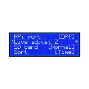
Go to your printer’s LCD menu > Settings > Lin.Correction > E correct, and then turn it off.
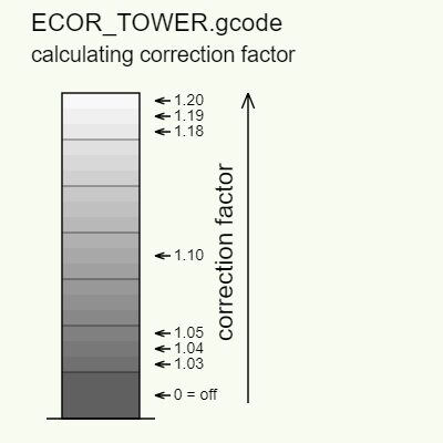
Download and print the Calibration g-code
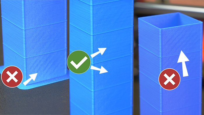
You will observe that some diagonal moire lines will appear on the tower. Find a place with the best surface on the calibration object.
Focus especially on 45-degree lines visible as a darker reflection
Most printers will have minimal distortion around the vertical center of the object (value 1.10), but yours might be different. Note your ideal value.
Enable the E-correction again in LCD menu -> Settings -> Lin.Correction->E correct. Adjust the value to the one that you were happy with.
Print something and see if the diagonal lines are still there. If so, please go back to step 3.